By admin on December 14, 2022
GPD Global can field upgrade your current DS Series dispensing system or MAX Series fluid dispensing system with many newer and more capable dispenses technologies. We can also bring that older PC hardware up to current standards, including the addition of the latest version of FLOware Software so you’re getting the full benefits of your dispenser with all the new features we have to offer.
Typical upgrade includes:
For a service upgrade proposal that fits your needs, use the New Support Ticket form or submit your request via email.
By admin on December 13, 2022
FLOware supports the use of USB devices for backups, transferring files, importing data, and exporting data. Most USB drives are compatible with FLOware. GPD Global provides USB drives known to work with FLOware with each precision dispenser. If you choose to use another USB drive with your dispenser, you should know the requirements for compatibility.
FLOware supports USB drive with the following partition types:
| Partition ID | Description | Compatibility | |
|---|---|---|---|
| dec | hex | ||
| 4 | 04h | FAT16 | Other operating systems. |
| 6 | 06h | FAT16B | |
| 11 | 0Bh | FAT32 with CHS addressing | |
| 12 | 0Ch | FAT32 with LBA addressing | |
| 14 | 0Eh | FAT16B with LBA | |
| 77 | 4Dh | Primary QNX POSIX volume on disk | QNX only (FLOware). |
| 78 | 4Eh | Secondary QNX POSIX volume on disk | |
| 79 | 4Fh | Tertiary QNX POSIX volume on disk | |
You can determine the partition type using a command prompt in FLOware.
ls /dev/pd*
This should generate an output similar to the following:
/dev/pd0 /dev/pd0t11
The above sample shows a single USB drive is connected with a single FAT32 partition (ID 0Bh / 11).
For a service upgrade proposal that fits your needs, use the New Support Ticket form or submit your request via email.
By admin on December 13, 2022
During startup, the database is read to properly load the motion control hardware. A utility named readuniversals reads from the database. Three messages should appear when readuniversals loads shown below:
readuniv:
DB Initialized OK
readuniv: Engine Found
readuniv: DB VER 2.9, SW VER 2.9 Is Acceptable
If the database is not loading correctly, you will only see the first message from readuniversals.
If may be possible to restart the database to finish booting. This workaround requires entering commands at the command prompt. To access the command prompt, press ctrl–C to stop the startup script. When the startup script is terminated, the following message displays:
DS9000 Startup Procedure Failed
After the startup failure message, you will see a command prompt (indicated by a line beginning with a dollar sign [$]). At this prompt, enter the following commands (these commands are case sensitive press enter after each line):
$ slay -9 dbsrv50
$ startup.sh; startx;
If your dispenser continues to hang during startup each time you boot, contact GPD Global support for a permanent solution.
For a service upgrade proposal that fits your needs, use the New Support Ticket form or submit your request via email.
By admin on December 13, 2022
A properly set system date and time are desirable for accurate data logging on your dispenser. A hardware clock on the CPU board maintains the current date and time even when the dispenser is powered off. The system date and time on your dispenser can be incorrect for many reasons including a reset of the CMOS, improper daylight savings settings, and more.
To set the system date and time and save the changes to the hardware clock, use the following steps:
The way the system date and time are displayed depends on the system initialization file. Before changing the date and time, you must verify the current configuration by accessing a command prompt and enter the following command:
less /etc/config/sysinit.1 | grep rtc
date Command on the DispenserThe date command can be used to display or set the system date and time.
Use the following format when setting the date and time where CC is the century, YY is the year, MM is the month, DD is the day, hh is the hour, mm is the minute, and SS is the second; each number is always two (2) digits. Only the hour and minute are required.
Changing the date requires root access.
date [[[[CC]YY]MM]DD]hhmm[.SS]
For example, if the current date is 11/5/2020 and the current time is 2:36:51 PM, you could use one of the following commands to set the system date and time to the actual time.
| to set | use command |
|---|---|
| date and time (if the date is wrong) | date 202011051436.51 |
| time only (if the date is correct) | date 1436.51 |
rtc Command on the DispenserThe rtc (real-time clock) command allows the operating system date and time to interface with the hardware clock.
During startup (see Checking the System Initialization File above), the rtc command links the current hardware time to the system date and time. This is handled in the system initialization file with one of the following commands.
| the hardware clock is in local time | the hardware clock is in UTC |
|---|---|
rtc -l hw | rtc hw |
If the hardware clock is using UTC, the clock can update for daylight savings time automatically.
To write the system date and time to the hardware clock, the set command is used. The hardware clock must be set with the same local time option as the system initialization file.
The rtc command requires root access.
If the system initialization file indicates the hardware clock is set to local time, use this command to set the hardware clock:
rtc -ls hw
If the system initialization file indicates the hardware clock is set to UTC, use this command to set the hardware clock:
rtc -s hw
For a service upgrade proposal that fits your needs, use the New Support Ticket form or submit your request via email.
By admin on December 13, 2022
Some dispensing system commands require root access to execute. Root access is indicated by a change in the command prompt; normal access is indicated by a dollar sign ($), root access is indicated by a hash symbol (#).
At a command prompt, enter the command su.
$ su
password:
#
* Characters are not shown while entering the password. Contact GPD Global for the root password.
For a service upgrade proposal that fits your needs, use the New Support Ticket form or submit your request via email.
By admin on December 13, 2022
I/O Definitions contain the digital input and output configuration parameters that control the way your fluid dispensing machine operates. Occasionally, you may want to change the configuration to accurately reflect hardware changes or to optimize your process.
To change the configuration:
IMPORTANT: DO NOT modify the GPD – I/O Configuration Definitions window. This window contains definitions of the configuration parameters; changes in this window do not affect dispenser configuration.
IMPORTANT: ONLY modify the GPD – Edit I/O Configuration window.
NOTE: You can press F2 to access a search dialog.
For a service upgrade proposal that fits your needs, use the New Support Ticket form or submit your request via email.
By admin on December 13, 2022
If your dispenser stops booting after displaying the S16: Unable to start the Flasher: MISC message, you can manually start the required software so you can continue using your dispenser. You should still immediately notify GPD Global of the error.
The Flasher tool primarily handles the status tower light and is required by the other FLOware tools for safety. Since Flasher tool is required for safety, Flasher must start before any other tools. If Flasher fails to start for any reason, the remaining tools also fail to start.
NOTE:The S16: Unable to start the Flasher: MISC is typically followed by the ERROR: DSmain Cannot Communicate with DSmisc. Refer to Log File. and ERROR: DSedit Cannot Communicate with DSmisc. Refer to Log File. messages. These messages indicate the other interface tools are also unable to start.
As a workaround, you can manually start the dispensing software required for your dispenser to function.
NOTE: Command completion is indicated by the appearance of the command prompt ($). If you do not see the command prompt after a few moments, press enter again and wait for the command prompt to appear.
DSflash &
DSmisc &After entering this command, the S07 message displays.
DSmain &
For a service upgrade proposal that fits your needs, use the New Support Ticket form or submit your request via email.
By admin on December 13, 2022
To successfully import a program, all the required items for the program must exist either on the dispenser or in the export file. To create an export file that includes all the required items, select the items.
As an example, a program named Program to Export is created. The program includes a reference to two vision patterns: one is named Pattern to Export – 1 and is used; the other is named Pattern to Export – 2 and is not used (see Program Header image). The program includes a shape named Shp 2 Export in the detail lines (see Program Detail image). The Program Mounts Table includes a material named Material to Export and specifies a tool named Head to Export 1 and a needle named 25 (see Program Mount image).
The shape named Shp 2 Export includes a reference to two vision patterns: one is named Pattern to Export – 3 and is used; the other is named Pattern to Export – 4 and is not used (see Shape Header image).
The material named Material to Export specifies a tool named Head to Export 2 and a needle named 25 (see Material Library image).
To create a complete export of the above example program that will import without any of the required items already created, each of the included items must be exported. All items required by the above example program can be exported together into a single file.
NOTE: Head to Export 1 is required by the program mounts table for the program named Program to Export (see Program Mount image).
NOTE: Head to Export 2 is required by the material library entry for the material named Material to Export (see Material Library image).
NOTE: Pattern to Export – 1 is required by header for the program named Program to Export (see Program Header image).
NOTE: Pattern to Export – 2 is required by header for the program named Program to Export (see Program Header image).
NOTE: Pattern to Export – 3 is required by header for the shape named Shp 2 Export (see Shape Header image).
NOTE: Pattern to Export – 4 is required by header for the shape named Shp 2 Export (see Shape Header image).
For a service upgrade proposal that fits your needs, use the New Support Ticket form or submit your request via email.
By admin on December 13, 2022
Can I set the default startup condition for my fluid dispensing system to always turn on the work area heater?
Work area heaters are useful in many applications when the product must maintain a certain temperature for proper dispensing (underfill applications, for instance). Work area heaters may take an extended amount of time to stabilize at the set point. Normally, the work area heaters are manually enabled and allowed to stabilize before an application requiring heat begins. Some fluid dispensing systems are only intended for heated applications and the work area heaters can be left on while the fluid dispensing system remains powered on. In this case, enabling the work area heaters during startup is advisable.
To enable work area heaters automatically during startup, modify the configuration of the fluid dispensing system to set EarlyHeat = True.
NOTE: Comment lines start with “#”.
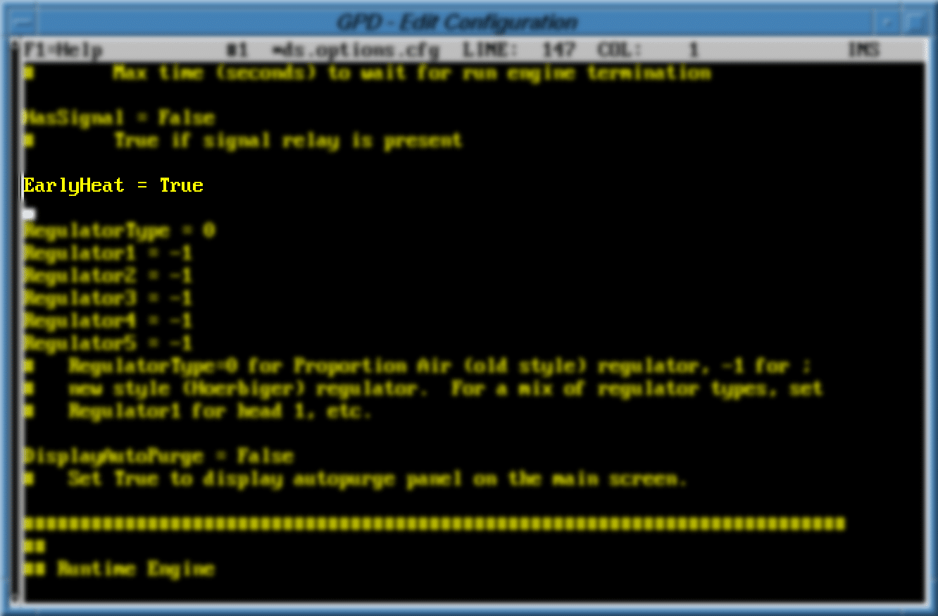
IMPORTANT: If a line reading EarlyHeat = False already exists, change the existing line instead of adding a new line.
For a service upgrade proposal that fits your needs, use the New Support Ticket form or submit your request via email.
By admin on December 13, 2022
Dispenser Configuration contains many configuration parameters that control the way your dispenser operates. Occasionally, you may want to change the configuration to optimize your process.
To change the configuration:
IMPORTANT: DO NOT modify the GPD – Configuration Definitions window. This window contains definitions of the configuration parameters; changes in this window do not affect dispenser configuration.
IMPORTANT: ONLY modify the GPD – Edit Configuration window.
NOTE: You can press F2 to access a search dialog.
For a service upgrade proposal that fits your needs, use the New Support Ticket form or submit your request via email.
By admin on December 13, 2022
DISK BOOT FAILURE, INSERT SYSTEM DISK AND PRESS ENTER
IMPORTANT: This message indicates a problem has occurred during dispenser boot up. The primary hard drive is unavailable or not selected as the first boot device.
To resolve this error:
For a service upgrade proposal that fits your needs, use the New Support Ticket form or submit your request via email.
By admin on December 13, 2022
Some system commands are not available directly from the FLOware menus.
IMPORTANT: All system commands are case sensitive and space sensitive.
NOTE: Execute system commands by pressing ENTER.
If FLOware is fully booted and the dispenser is homed, an XWindows Shell window is accessible using the menus:
If FLOware is unable to finish loading or the dispenser cannot be homed, an XWindows Shell window is accessible from the background:
NOTE: If the background logo is not accessiblable, enter a password that allows system access. System access reveals a very small (2 pixels tall) part of the background at the bottom of the sceen.
If FLOware cannot be started, a shell is available during the boot sequence:
For a service upgrade proposal that fits your needs, use the New Support Ticket form or submit your request via email.