3.5. Teach subboards program
The Multiple option enables you to teach a subboard program that is then automatically applied to a panel of multiple, identical subboards.
Procedure
- If the system and laptop are not already
connected and if the robot is not already homed:
- From the main button bar, click the Connect button. Then click OK on the success prompt.
- From the main button bar, click the Home button.
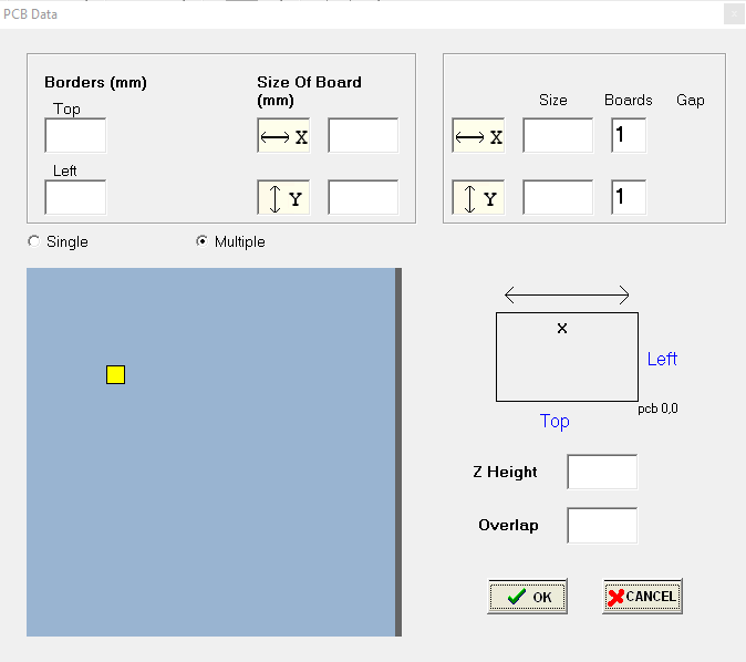
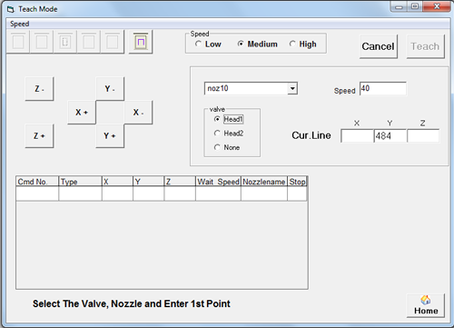
- From the main menu, select .The PCB Data window displays.

- Choose the Multiple option to program an array of subboards
in a panel.To program a single board instead, follow the Teach a program instructions.Fields for multiple subboards display.
- Enter board data:
- Enter board dimensions in the Borders and Size
of Board fields in millimeters.
Parameter Definition Borders Dimensions of pallet supporting the subboards; measured from the PCB 0,0 point (bottom right hand corner). Size of Board Total X and Y dimensions of the pallet supporting the subboards. - Enter the X and Y subboard dimensions in Size in millimeters.
- Enter the number of subboards in the pallet in Boards for X and Y.
- Enter the distance between subboards in Gap in millimeters for X and Y.
- Enter a value for Overlap in millimeters.This is the amount of overlap to be used for area fills. This value should be less than the value defined for Nozzle Diameter.
An image of the subboard array displays based on your input.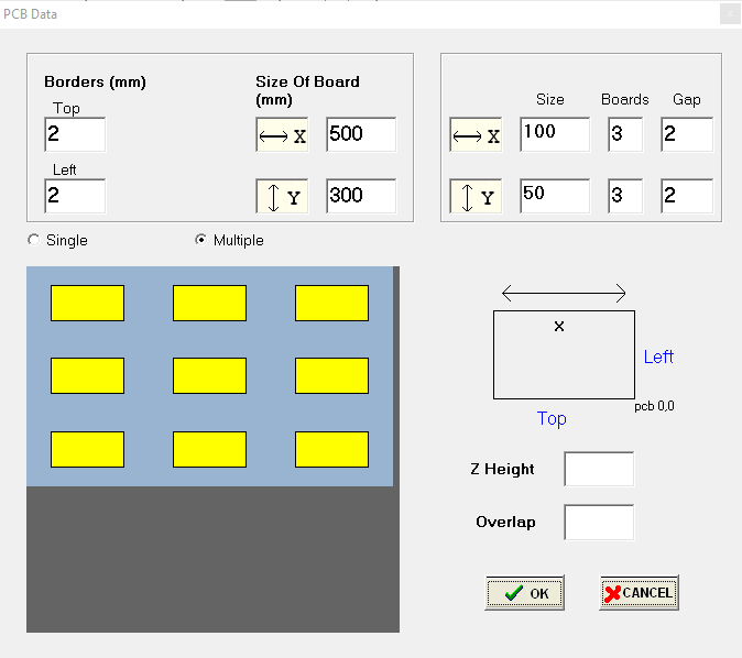
- Enter board dimensions in the Borders and Size
of Board fields in millimeters.
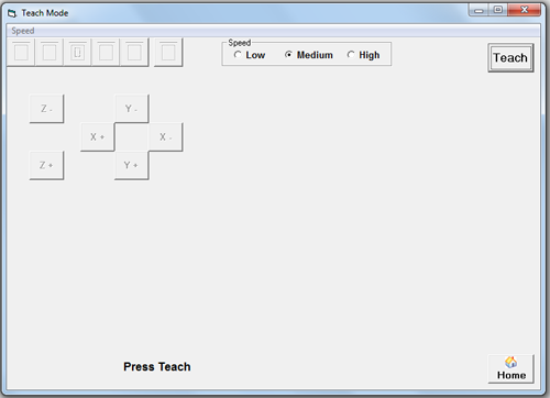
- Click the OK button to continue.The Teach Mode window displays.
-
Note
General instructions are typically provided in the bottom left hand area of the window. - Click the Teach button.The gantry immediately moves to the front of the work area, positioning Head1 to the right of the conveyor board stop.The operation buttons in the button bar become available.
- Teach a point:
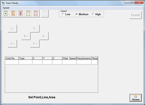
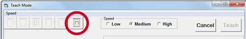
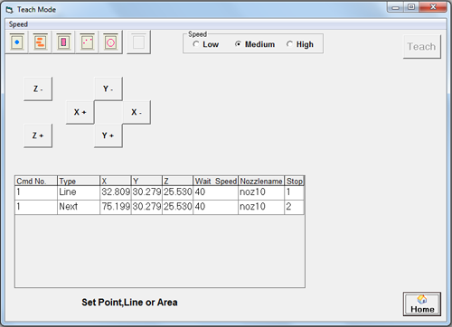
- Click an operation type button: Line, Area
Fill, Arc, or Circle.Nozzle, head, and operation parameter fields display.
- Select desired head.The head immediately toggles downward.
 Important
- Select desired nozzle.
- Using the provided XYZ buttons, move the selected
head to desired XYZ coordinates.
 CAUTION
- Select desired speed.
- Click the Set button to firm
the point values.
 Screen instructions prompt you to enter the next point.
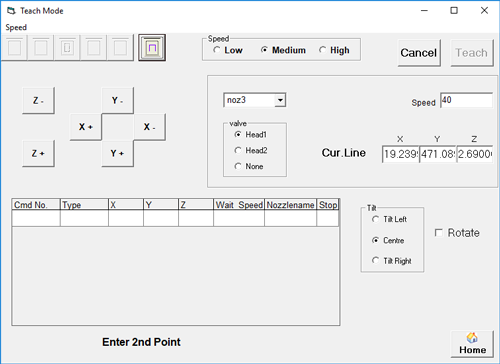
- Click an operation type button: Line, Area
Fill, Arc, or Circle.
- (Optional) Set
up tilt and rotate for Head1:The tilt and rotate function only displays on SimpleCoat TR models and only applies to Head1. Refer to Tilt and rotate considerations for additional details.
- Select the program pattern step to be dispensed at an angle by Head1.
- Select the Rotate check box.Head1 valve rotates 90 degrees to achieve rotation.
- Using the provided XYZ buttons, move the Head1 nozzle to desired XYZ coordinates.
- Select the desired option: Tilt Right or Tilt
LeftHead1 valve tilts 45 degrees.
- Click the Set button to firm the point values.
- Teach additional program steps, as needed, following
the same procedure described in the prior steps.
- When you are done adding steps to the program, click the Home button located in the lower right hand corner of the window.
- When prompted, select YES to save data.
- When prompted, select OK to save file.
Results
The program is now ready to download and run.