3.2. Calibrating heads
Head calibration requires the system be set to maintenance mode and is typically performed during initial setup.
Before you begin
Tools and equipment required:
- Calibration plate
- Allen key: 2 mm
- Valve mounted in each head position to be calibrated
Procedure
- If the system and laptop are not already connected
and if the robot is not already homed:
- From the main button bar, click the Connect button.
- Click OK on the success prompt.
- From the main button bar, click the Home button.
- Set the Run/Maintenance keyed lock on the front control panel to Maintenance.
- If you’ll be calibrating a spray nozzle in either head position, manually unscrew the spray cap from the spray nozzle and set it aside.
- Slide the calibration plate into the work area on the
conveyor rails until it is snug against the board stops at 0,0 position.
Figure 2-2. Calibration plate (PN 23116001) 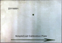
- Calibrate Head1:
- From the main menu, select The Head Calibration window displays.
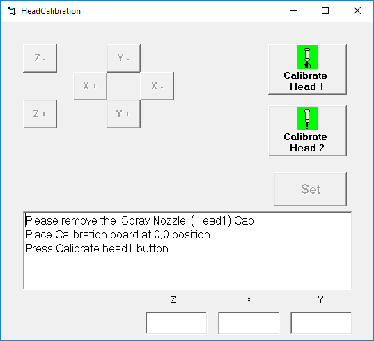
-
Click Calibrate Head 1. CAUTION
- Using the X and Y jog buttons, center the tip of the needle over the hole in the calibration plate.
- Using the Z axis jog buttons, adjust the tip of needle so it is positioned just above the surface of the calibration plate.
- Click the Set button.
- Click the OK button for each location prompt, and then select YES for the overall offset prompt.
- Use the Z- button to raise the needle upward, away from the calibration plate.
- From the main menu, select
- Calibrate Head2:If this head will not be used, skip this step.
- Click Calibrate Head 2.Head Calibration window.
- Using the X and Y jog buttons, center the tip of the needle over the hole in the calibration plate.
- Using the Z axis jog buttons, adjust the tip of needle so it is positioned just above the surface of the calibration plate.
- Click the Set button.
- Click the OK button for each location prompt, and then select YES for the overall offset prompt.
- Use the Z- button to raise the needle upward, away from the calibration plate.
- Click Calibrate Head 2.
- Remove the calibration plate from the work area and store for future use.
- Close the Head Calibration window.
- Click the Home button.
- Set the Run/Maintenance keyed lock on the front control panel to Run.